OVERVIEW
Timeline: October 2018 (3 weeks)
Focus: Mechatronics | Mechanical design | Electrical design | C Programming
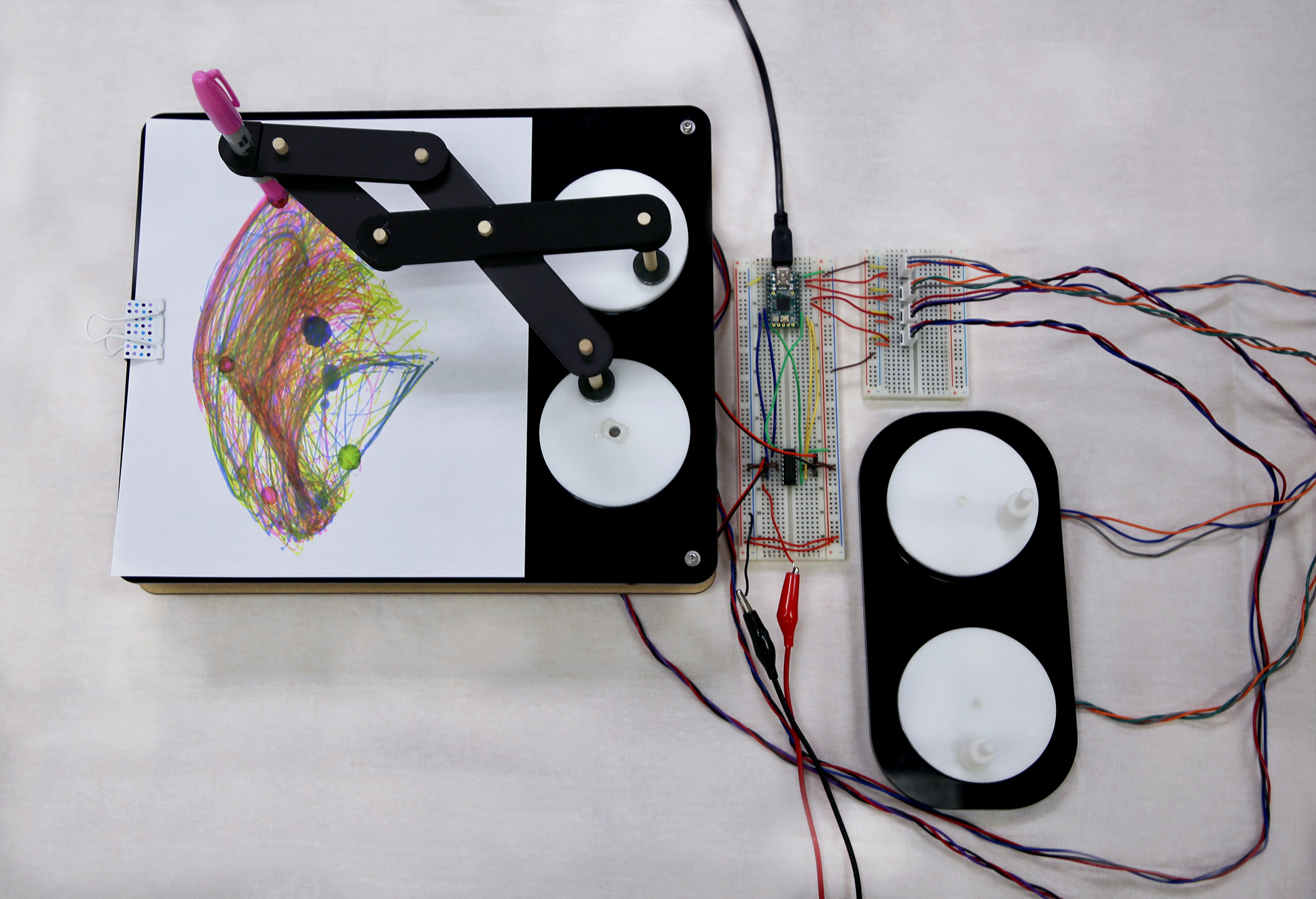
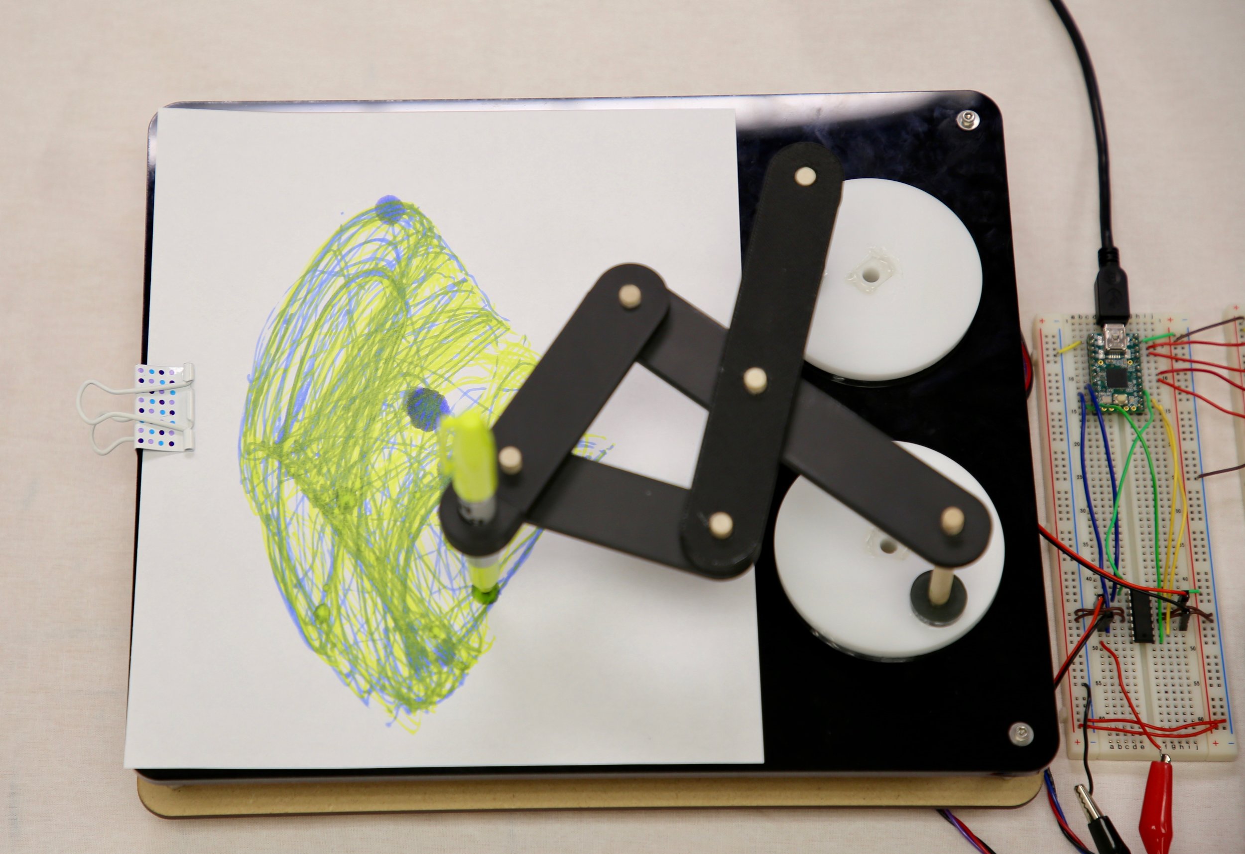
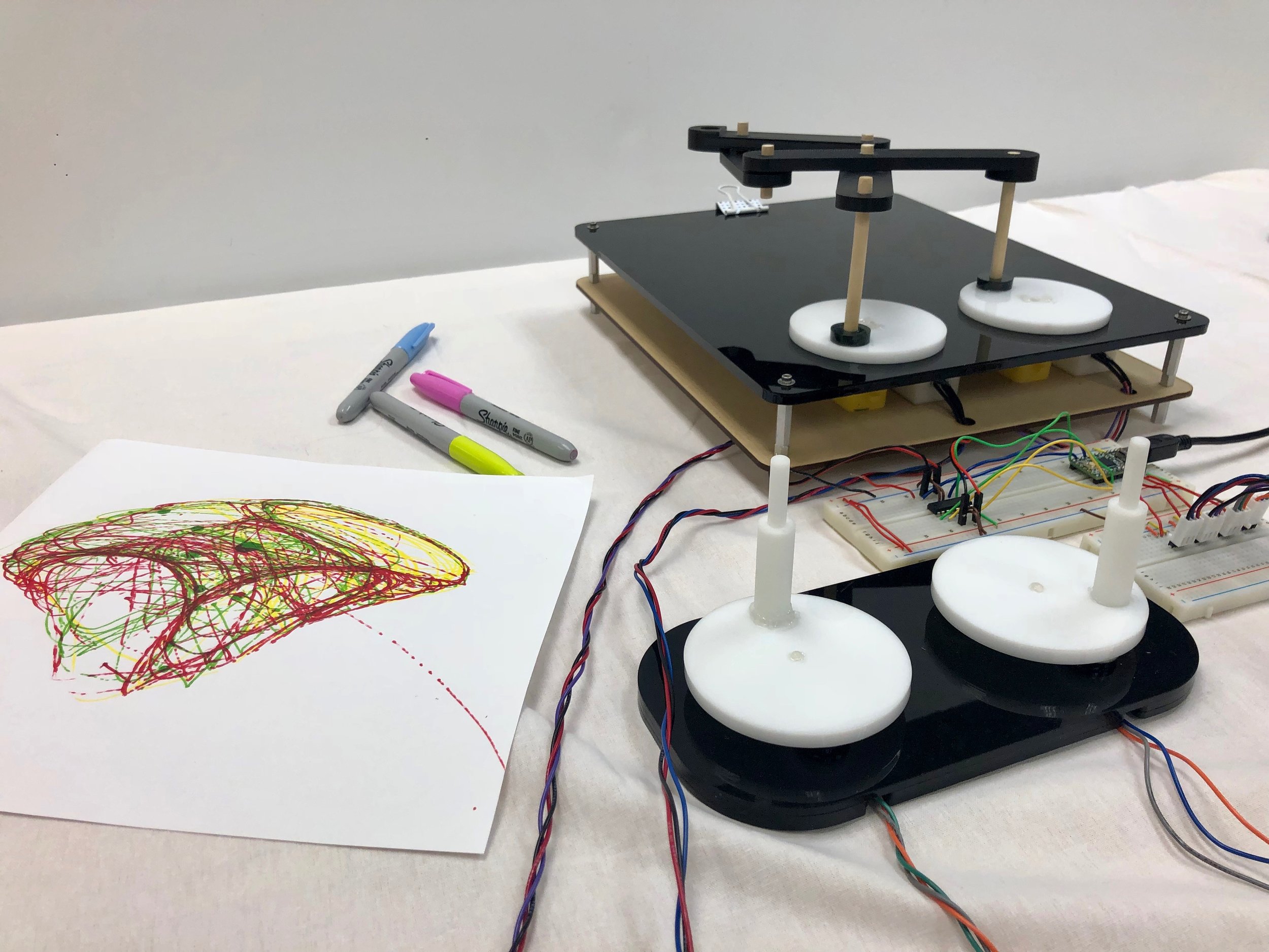
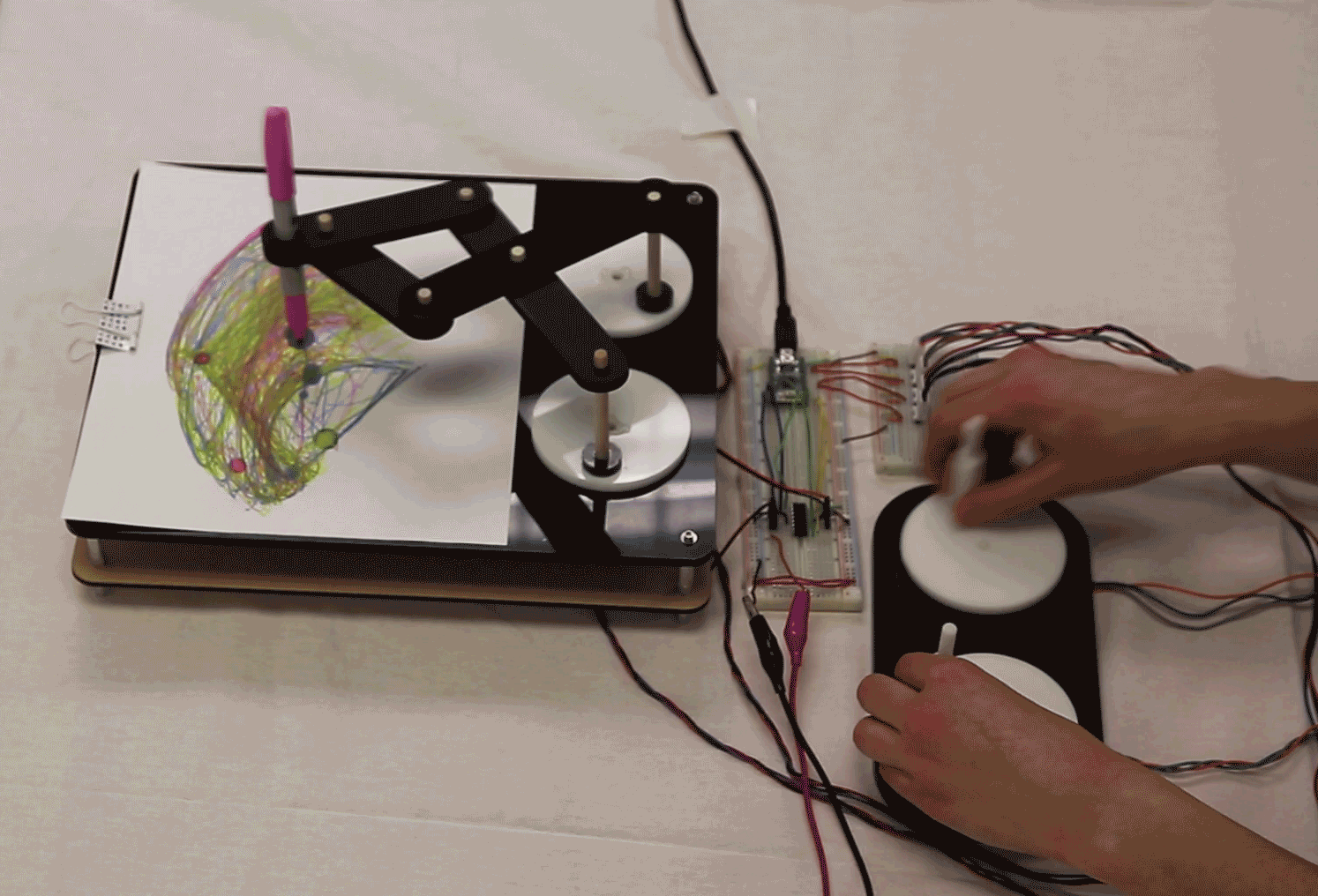
This project challenged us to design a remote manipulation device (“Waldo-style” robot system). The system consists of an input side that records motion, which can be used to move a remote device (output side) in a similar motion. Following my belief that projects should be both purposeful and fun, whenever possible, I designed a pinto-graph type drawing machine. This system has two independently controlled inputs and has two replicate outputs with a 4-member scissor linkage attached that enables a marker to draw. The input side senses movement with two potentiometers, and the output side replicates/mirrors the moment, actuated by two DC motors. Each motor is attached through a gear transmission to a potentiometer, which is used for output position sensing and control.
DESIGN
How it works
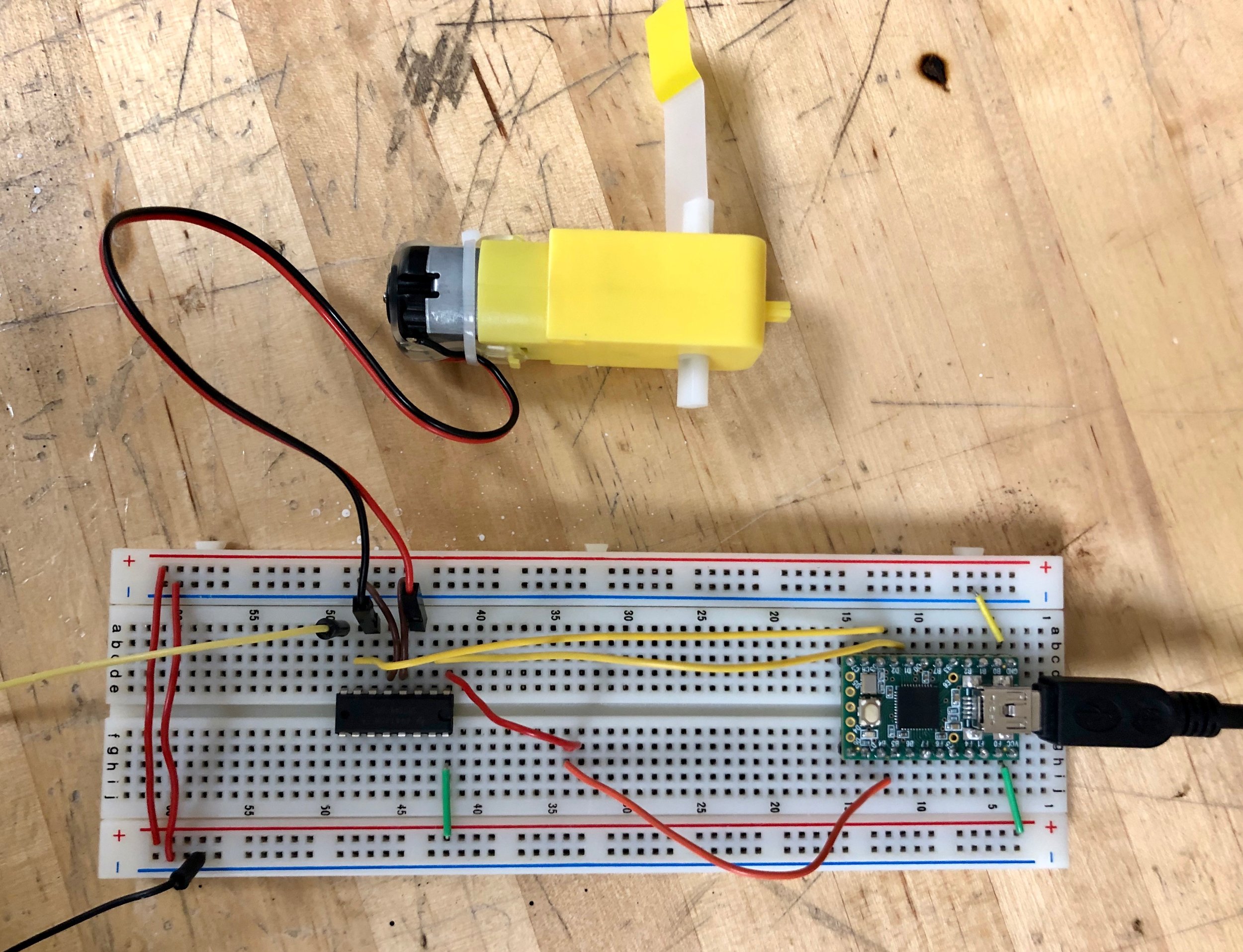
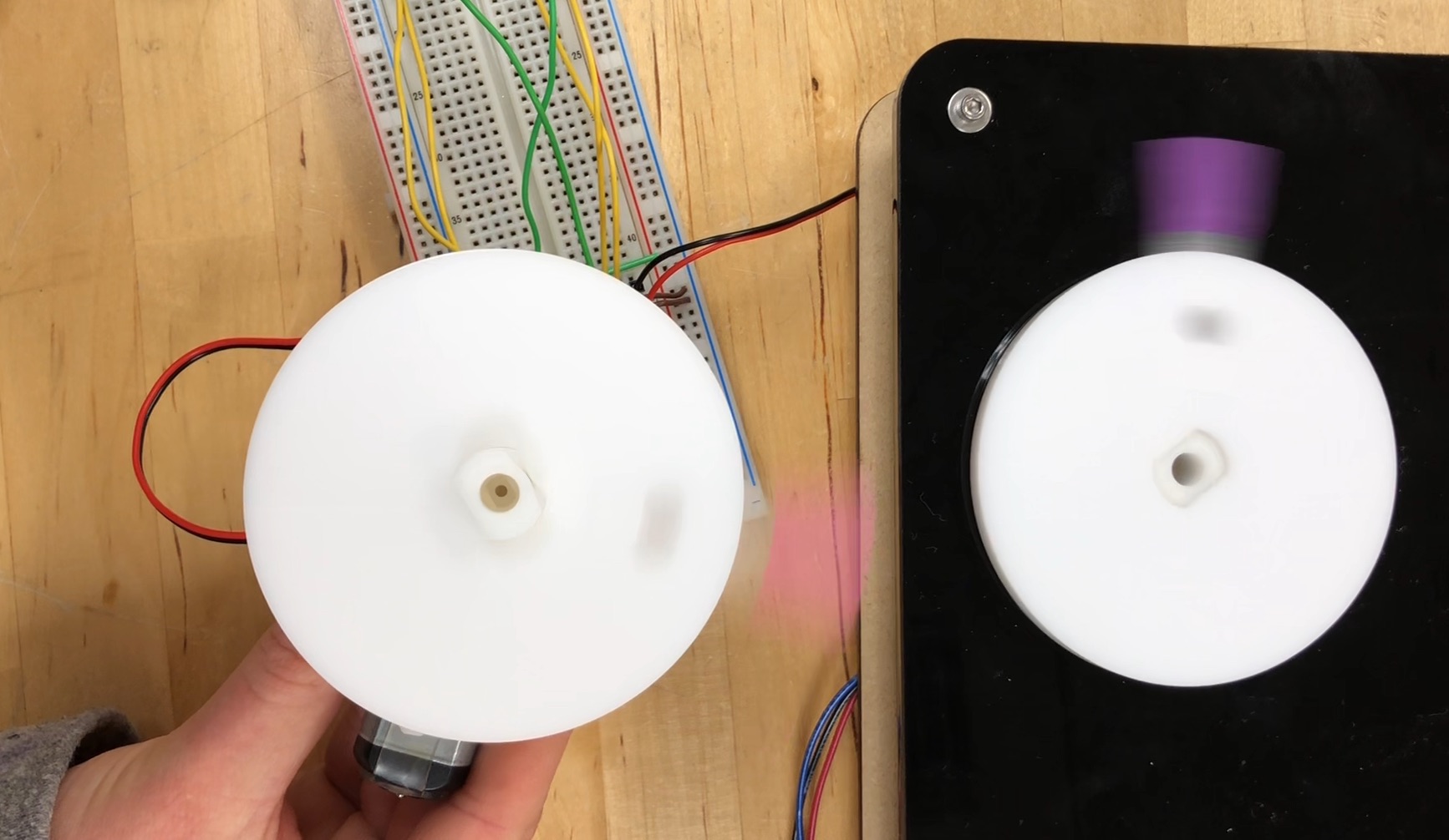
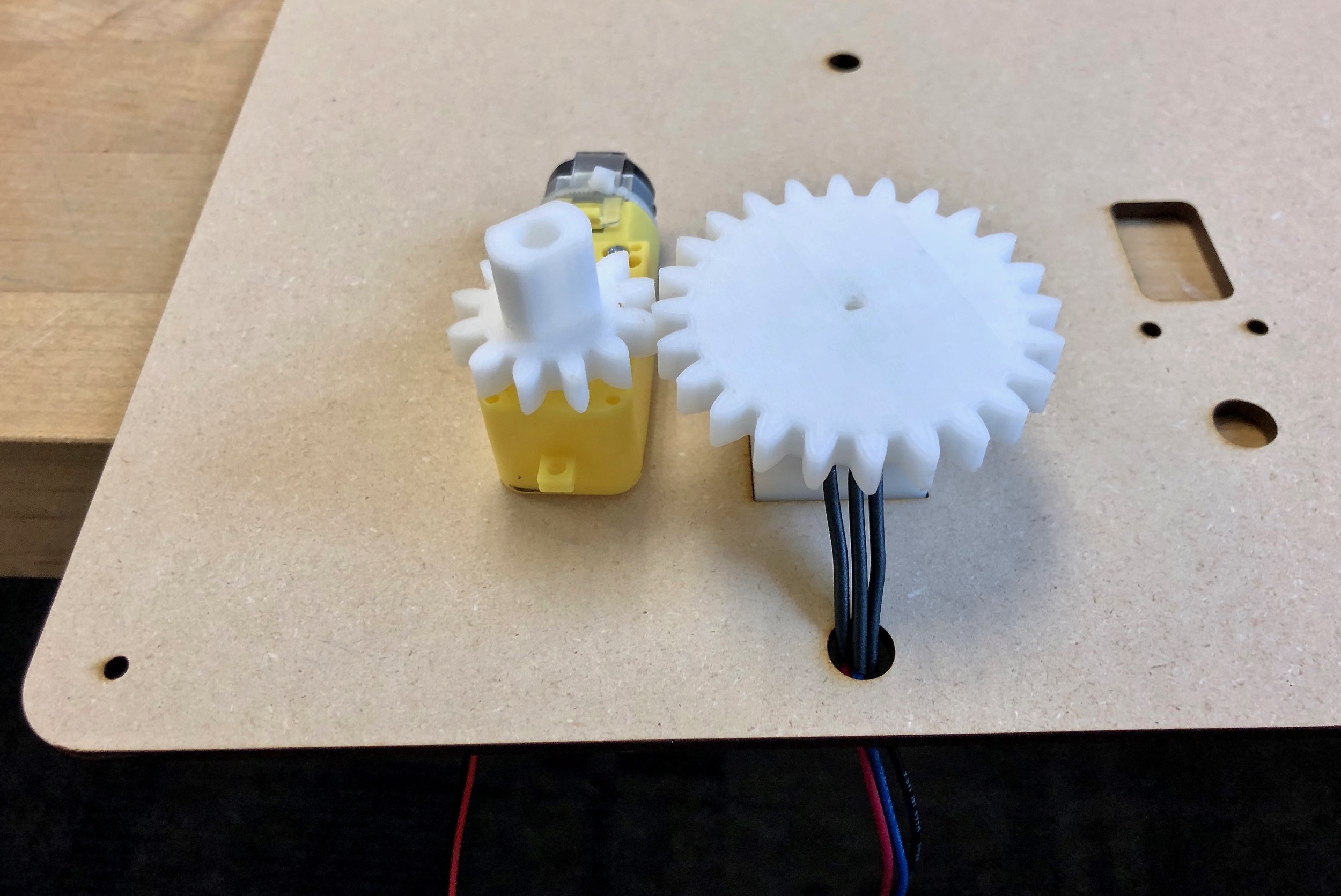
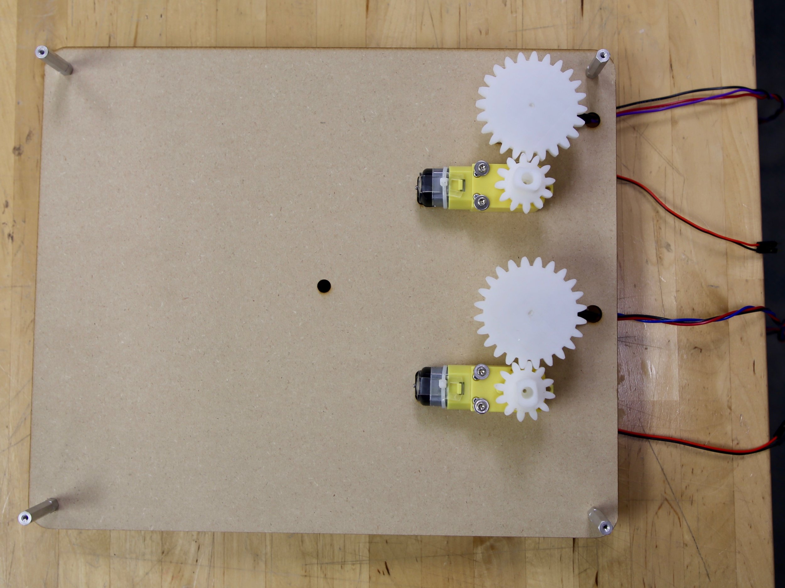
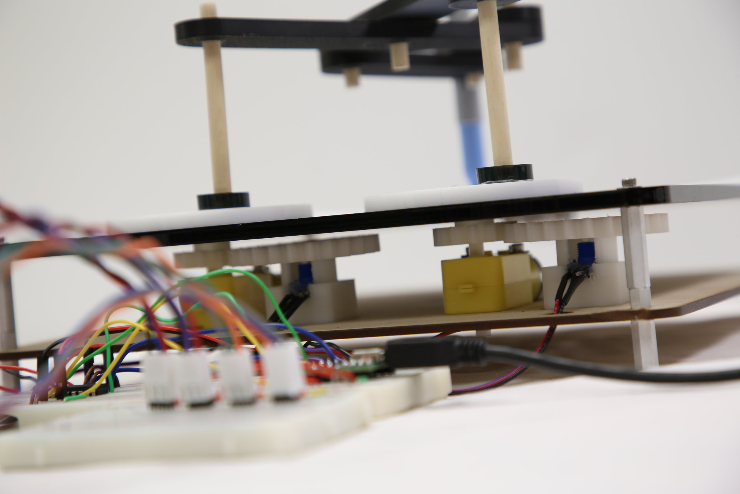
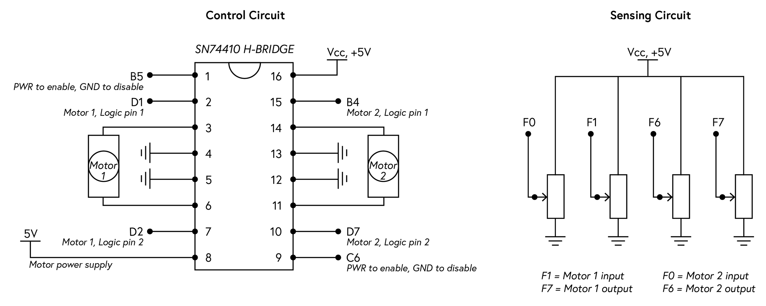
In this project, I used the Teensy 2.0 micro controller (ATmega32U4) and programmed in C. The sensing (input) side of the system takes in analog input from potentiometer position, and the program converts the input into a digital output. Proportional error and PWM are used to control the speed of the motors. The program calculates the difference in current motor position and previous motor position to determine the output movement necessary. This is measured through potentiometers which are connected to the motors through a gear transmission. A 2:1 gear ratio is used to slow down the speed of the output movement. Digital output logic to an H-bridge controls the direction of the two DC motors.
Mechanical design


Electrical design
PROCESS
Design process & documentation
Throughout the project duration, I built the final design incrementally. First, I worked on getting the electronics to work. Next, I prototyped mechanical components of the design, including the gears and linkage. Next, I integrated the mechanics and electronics of a single degree-of-freedom. Finally, I integrated the second degree-of-freedom and made minor adjustments to the complete system.