OVERVIEW
Timeline: November - December 2018 (3 weeks)
Focus: Mechatronics | Mechanical design | Electrical design | Programming
Collaborators: Anna Estep | Tommy Mulroy | Sean Trahan
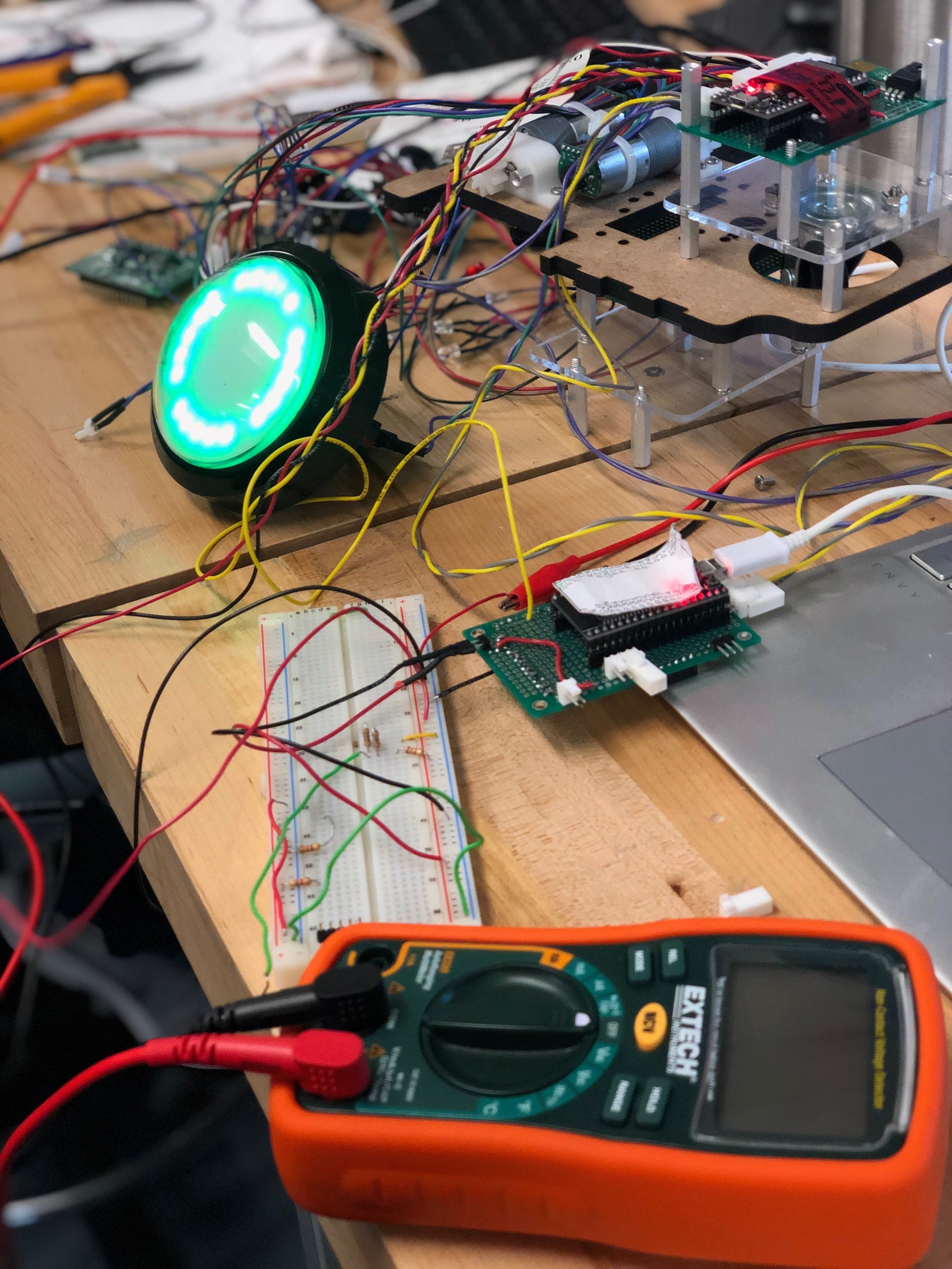
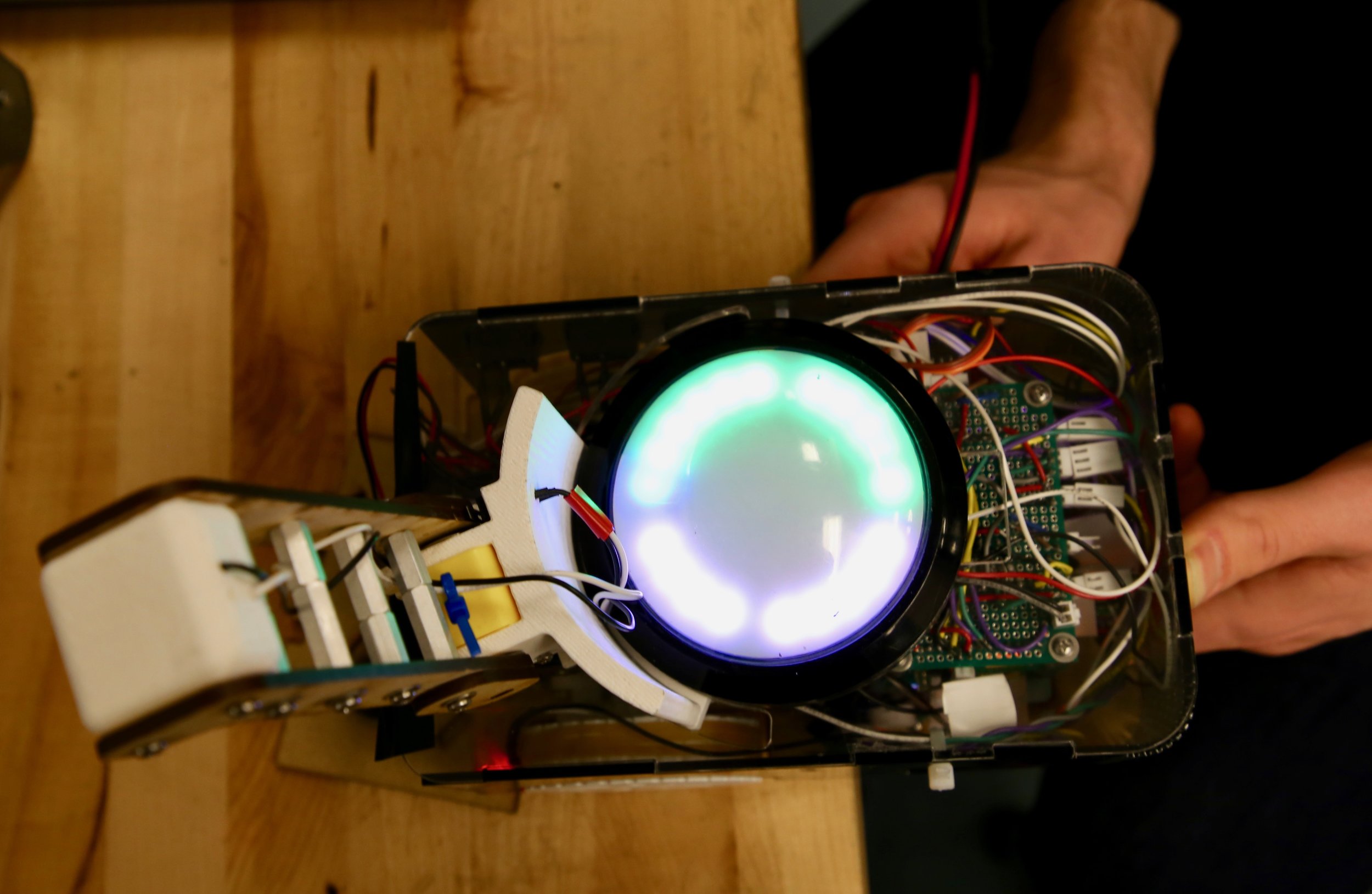
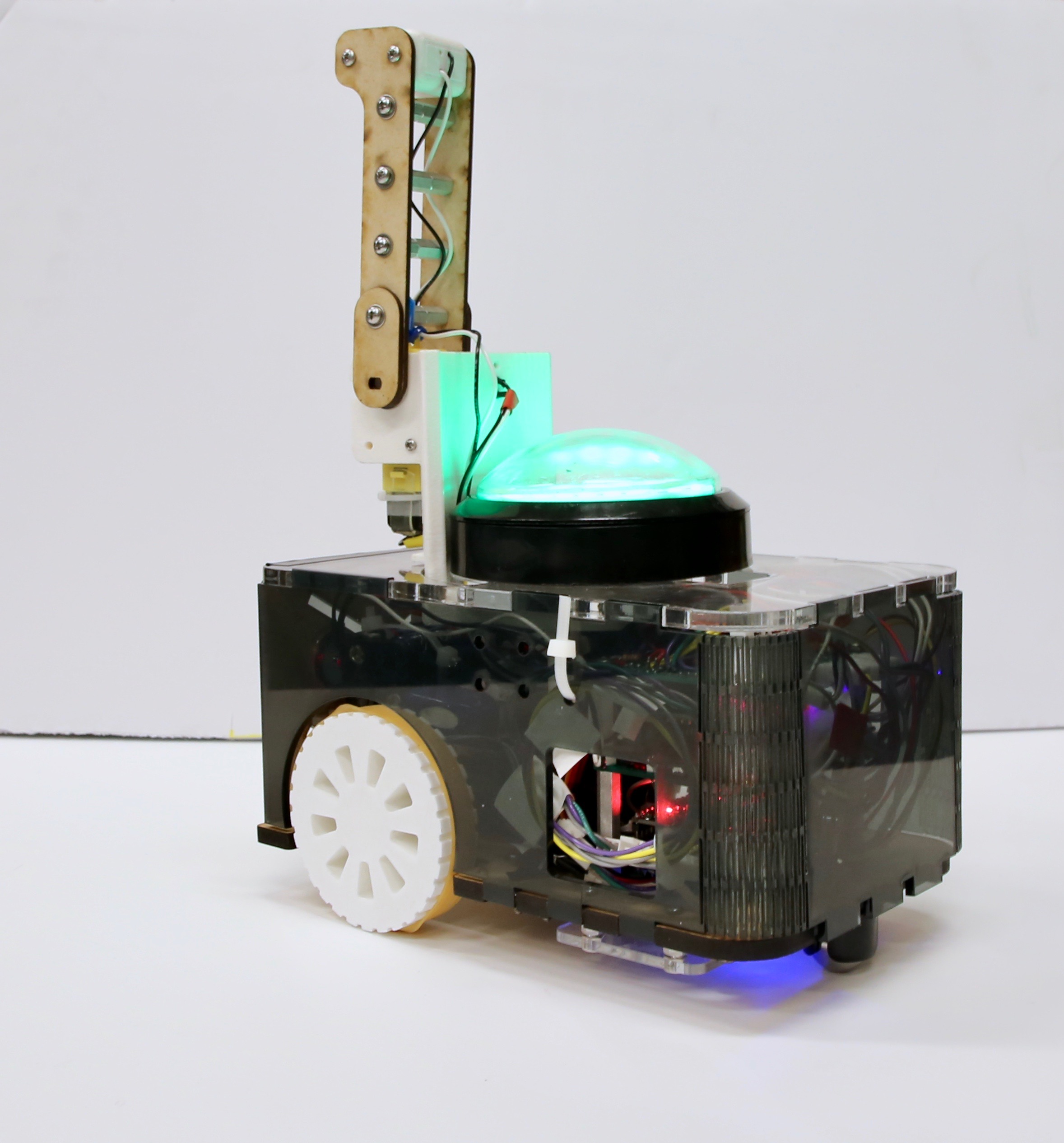
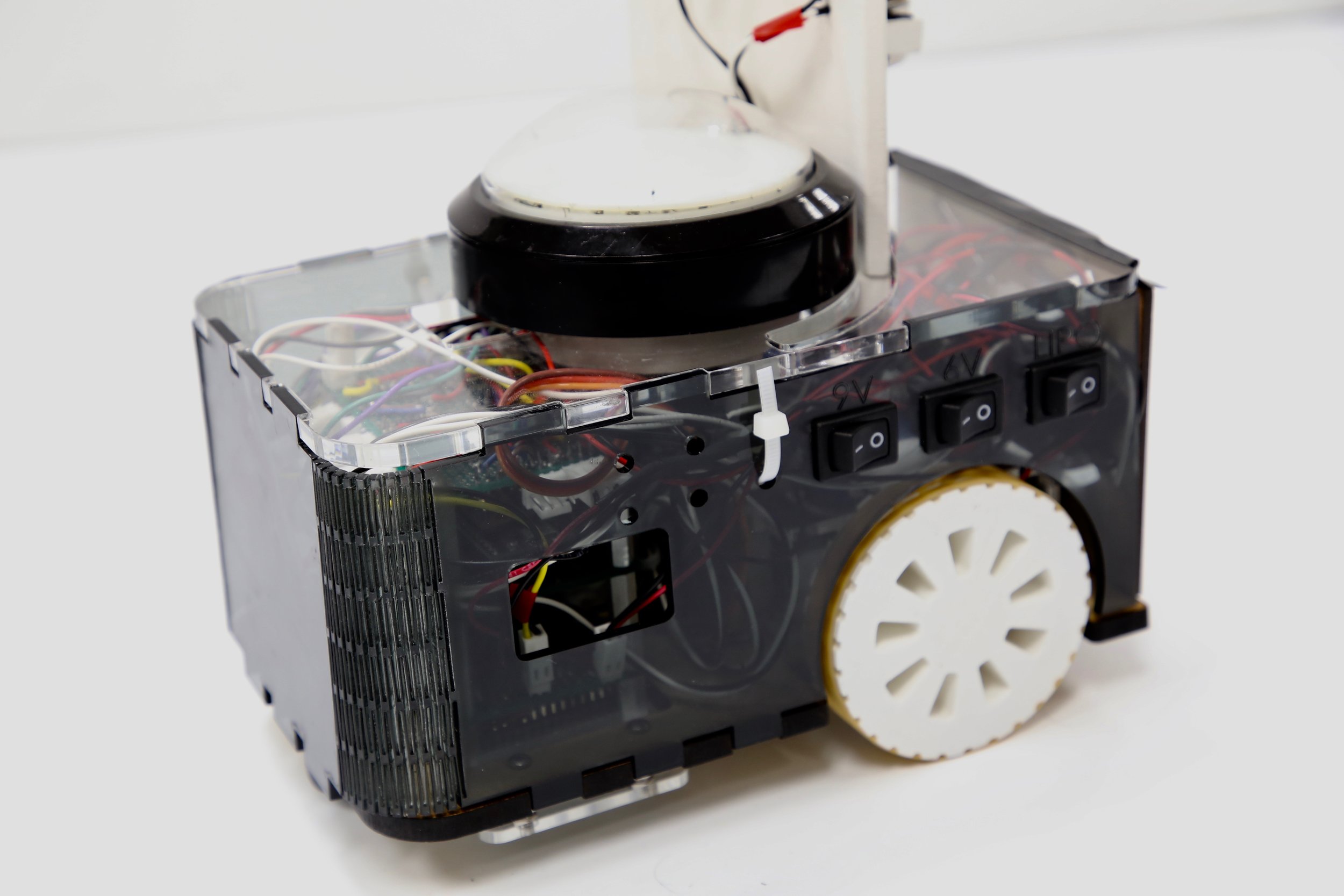
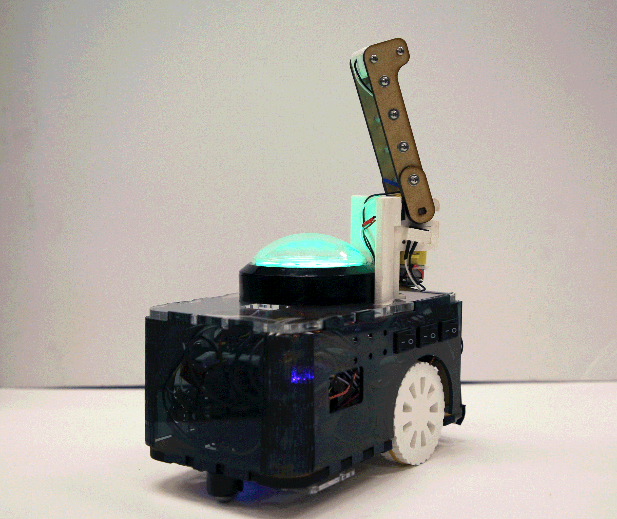
This project challenged us to design a remote controlled “battle bot” robot that can play in a multiplayer battle arena style game. The objective of the game is to deplete the health of the opposing team’s nexus (home base), while protecting your own. Robots can also deplete the health of opposing robots by hitting them with their weapon (achieved by pressing the top hat button rather than inflicting physical damage). Robots can recover from damage if they are able to detect “healing lights” which flash throughout the game at specified frequencies.
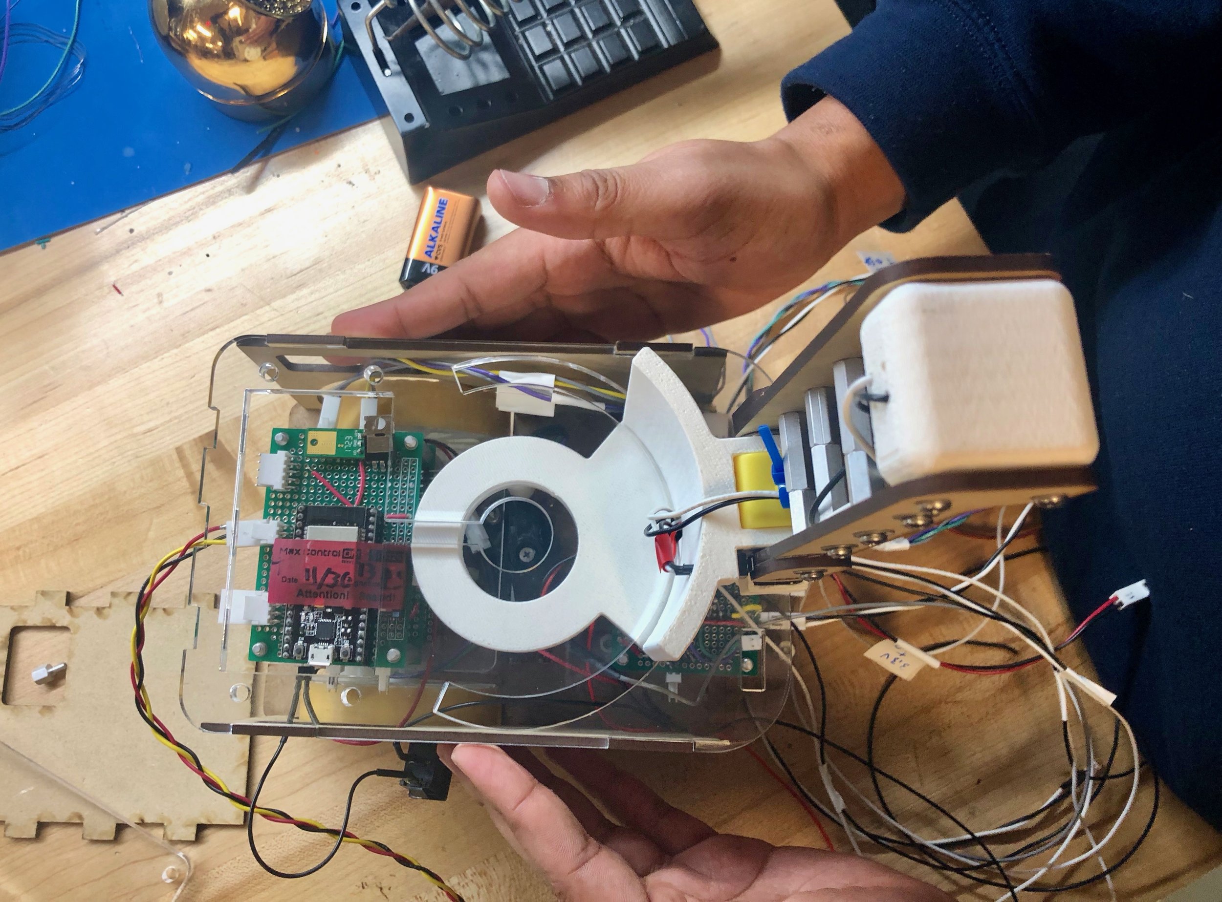
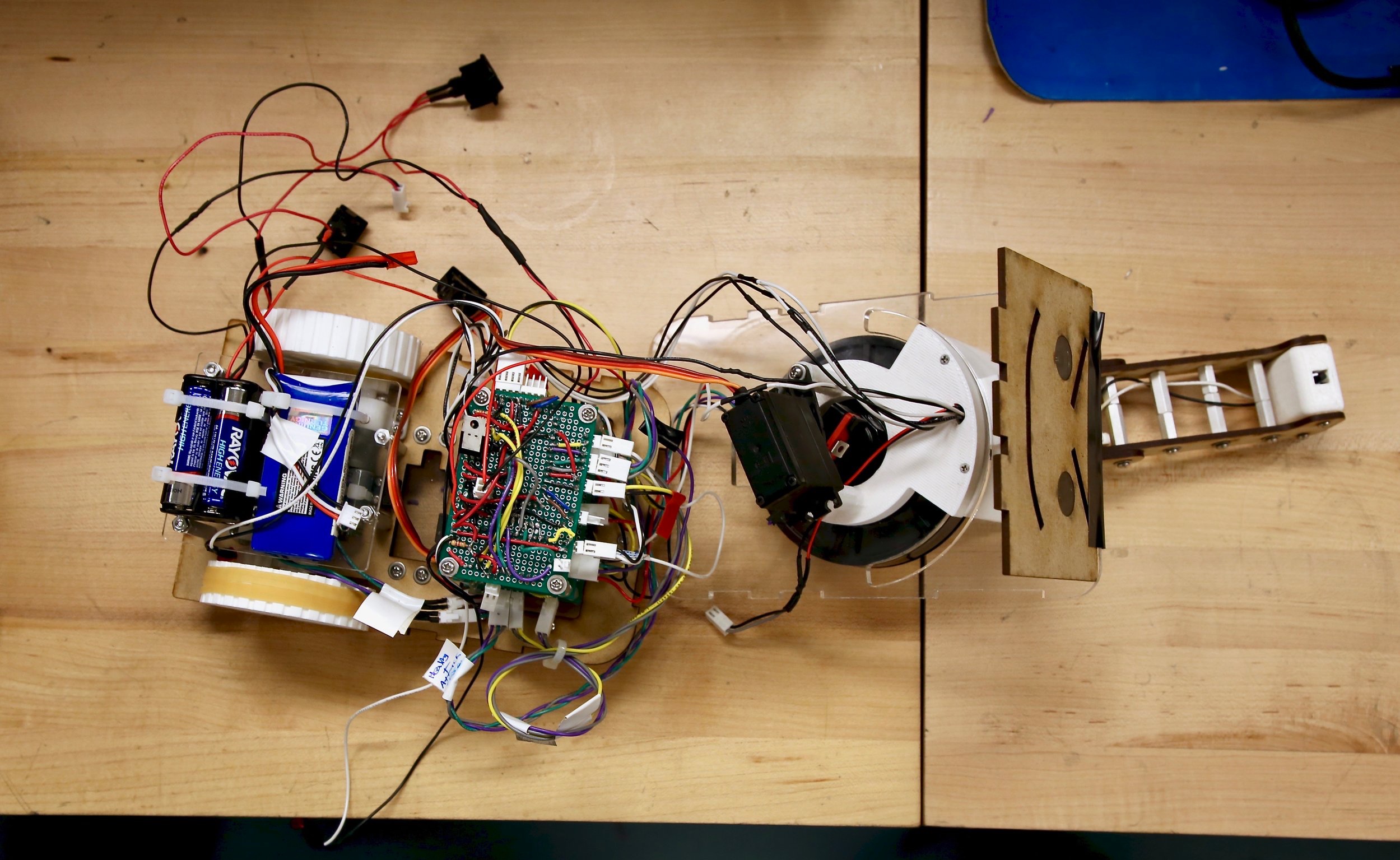
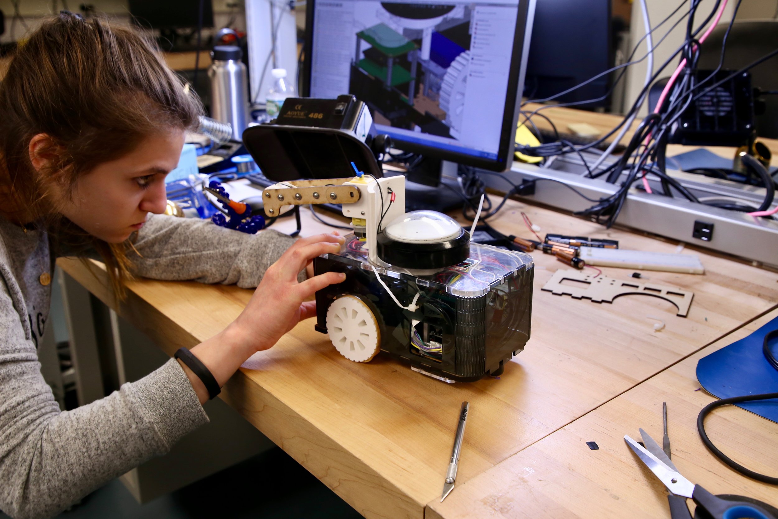
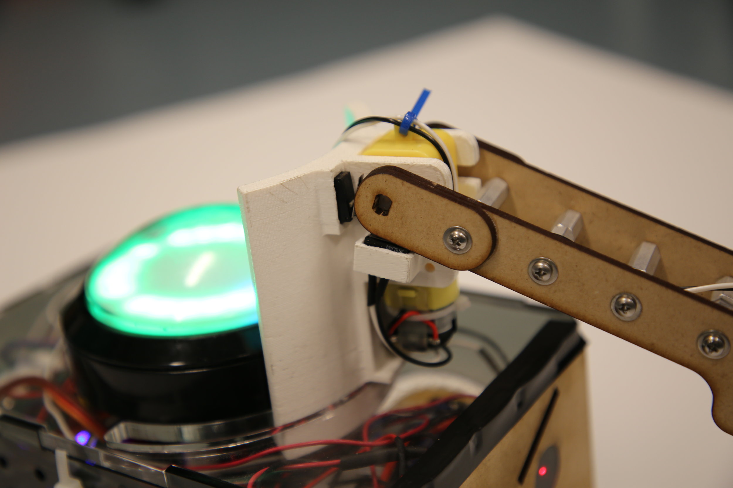
Our team strived to design and build a robot with robust design in all facets: software, electrical and mechanical. The robot’s functionality includes: a differential drive steering system that receives driving commands via WiFi from joystick input in the controller, a two degree-of-freedom hammer weapon arm, and the ability to sense and differentiate the PWM frequency of “healing lights” at the specified frequencies. Additionally, our team took on the complex challenge of designing and implementing a shield that rotates around the top hat button to further protect it. This 90 degree shield rotates 175 degrees around the top hat button and attaches to the weapon arm, giving the weapon an additional degree of freedom. Successfully implementing this was one of the most challenging aspects of the design, however we believe it is one of the most impressive parts of our robot and time well-spent.
DESIGN
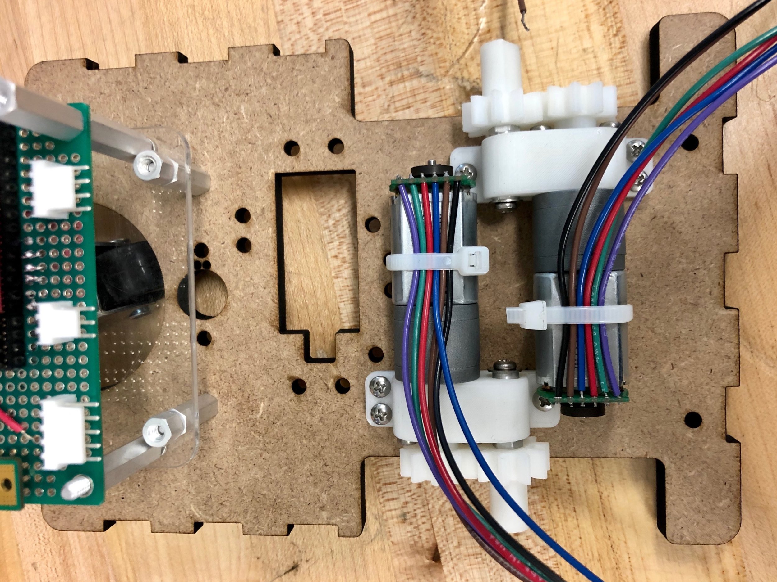
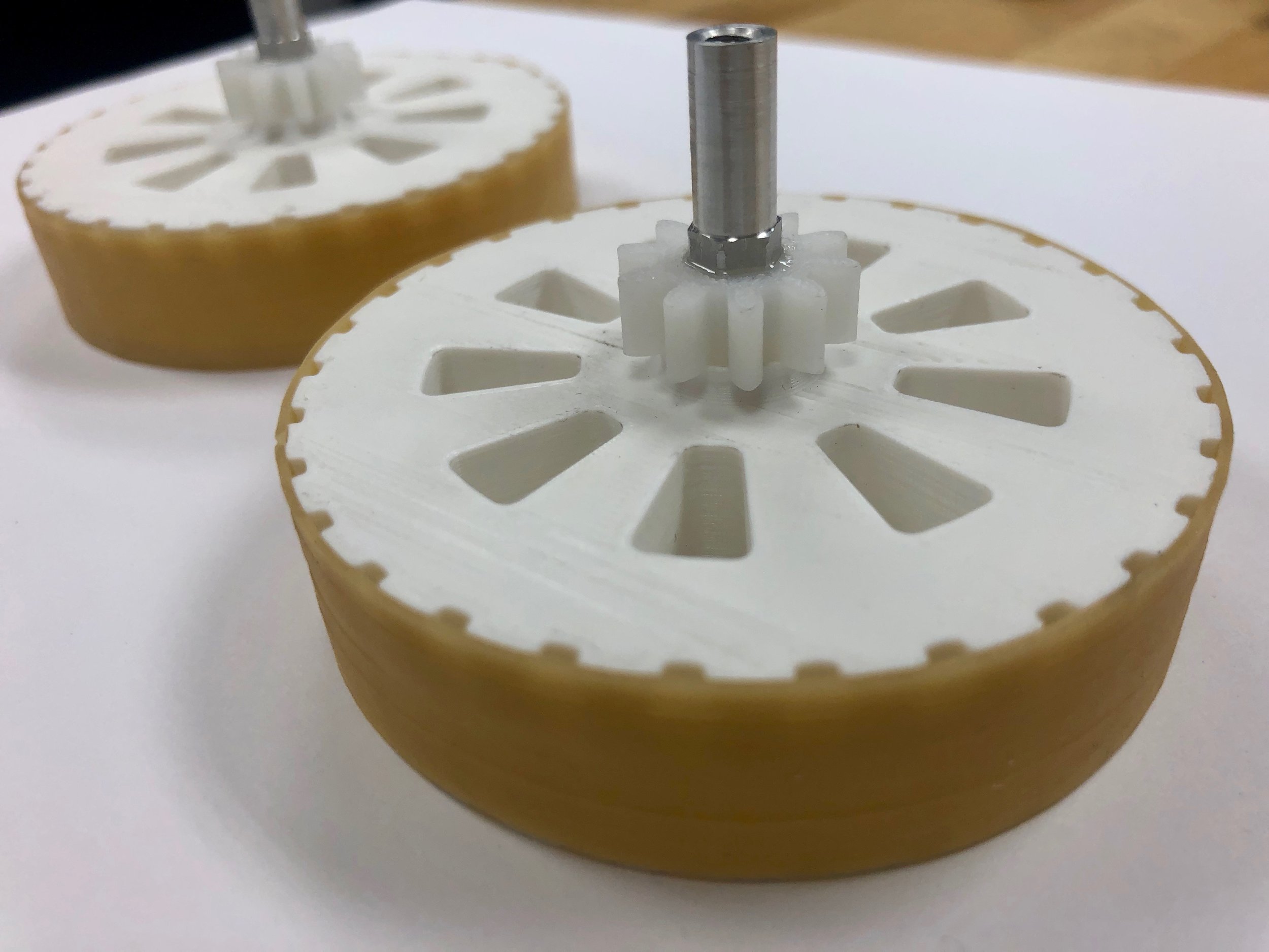
Mechanical design


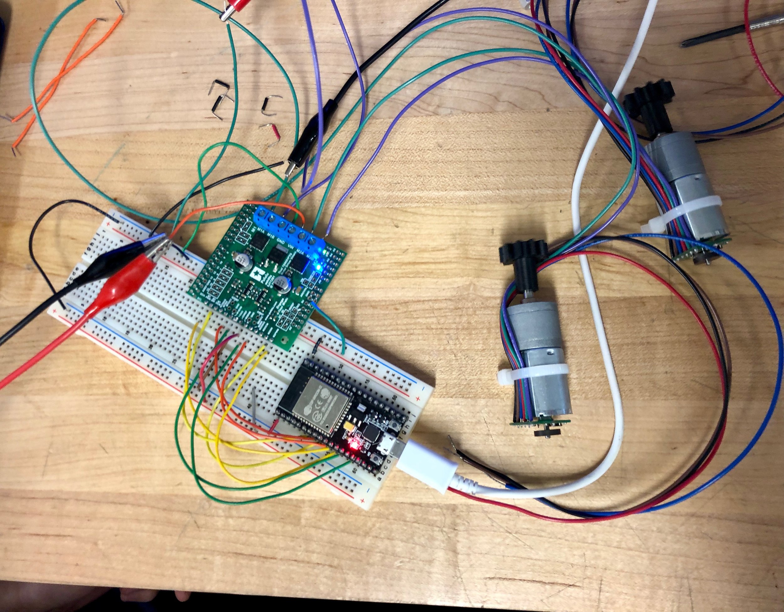
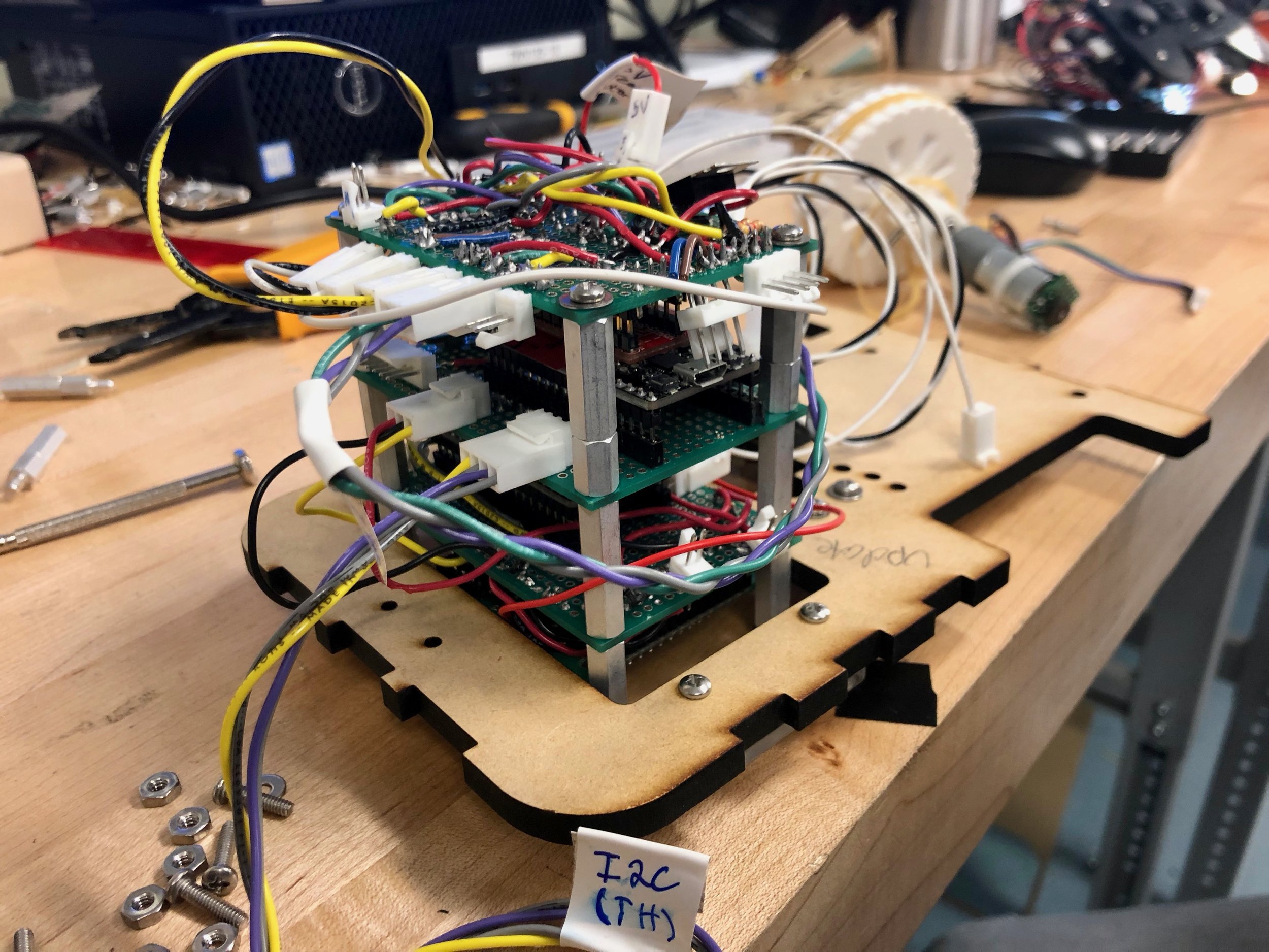
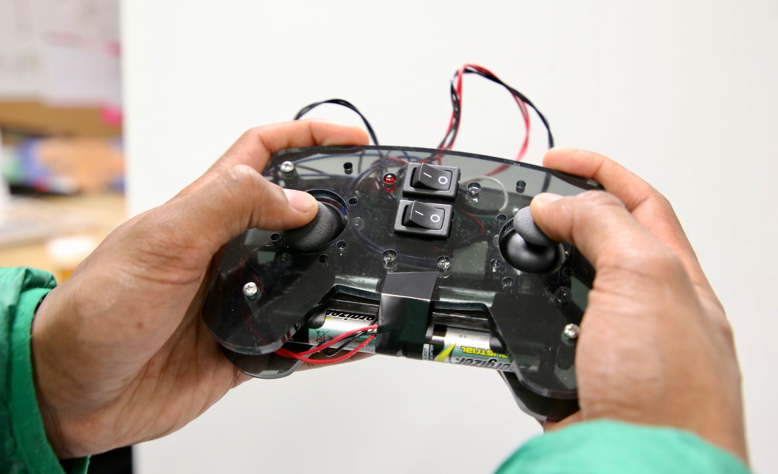
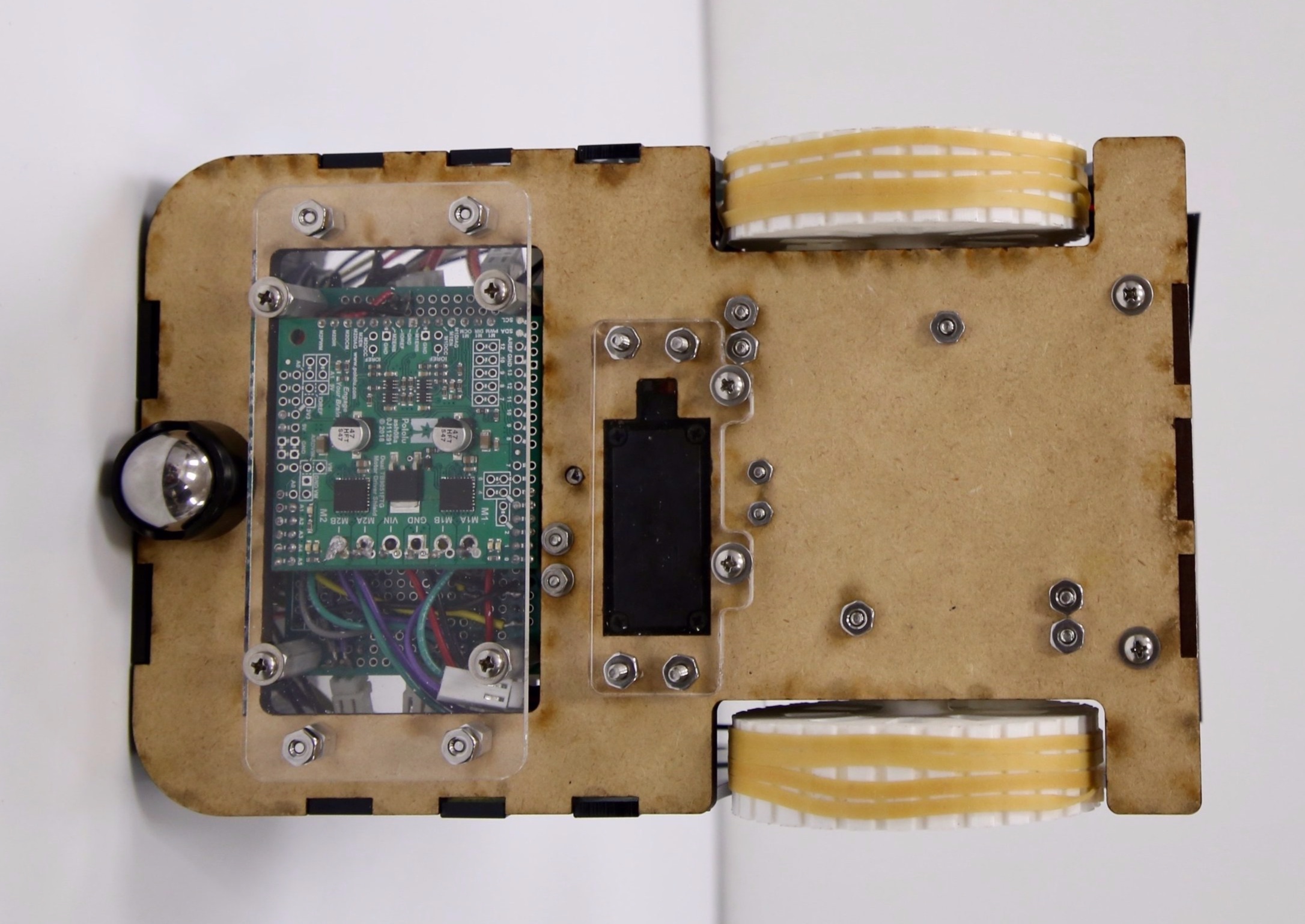
Electrical design and processor architecture
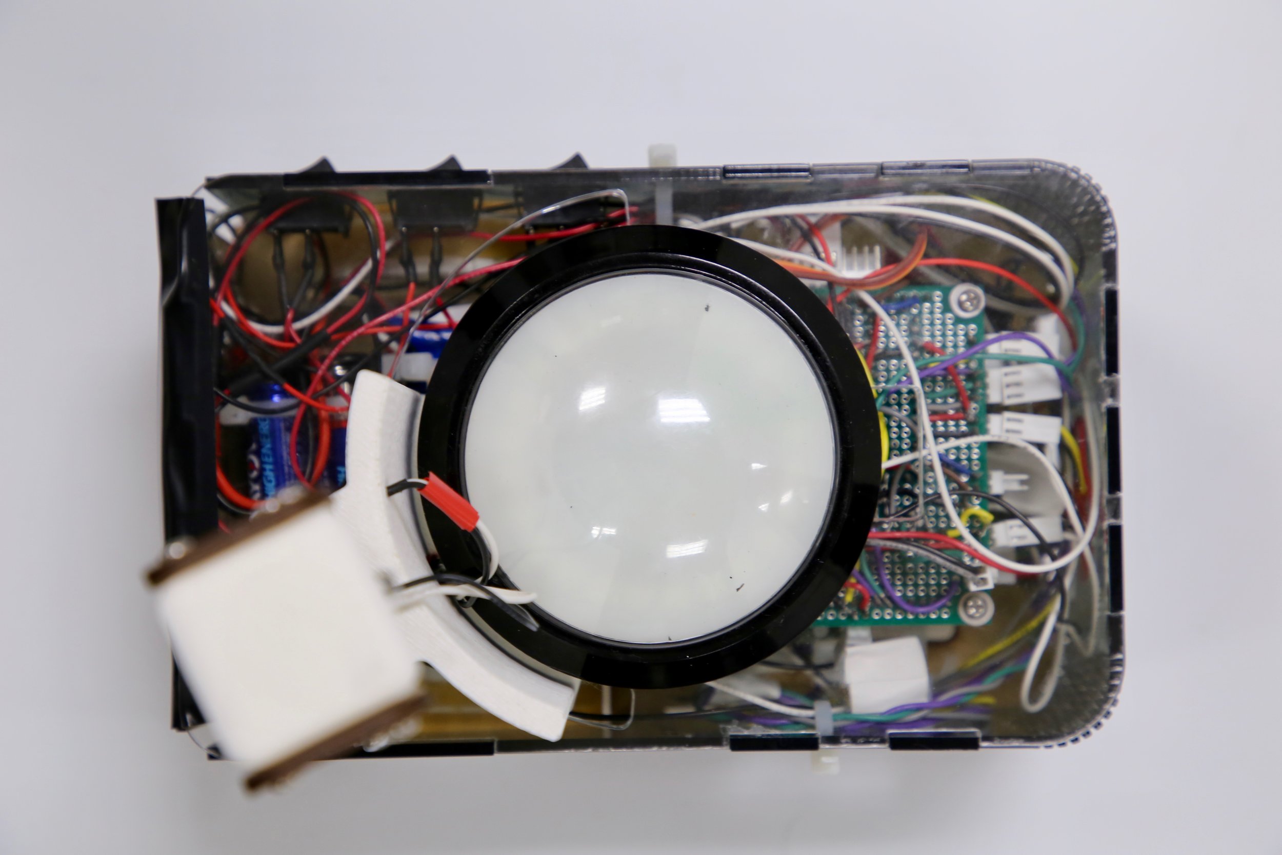
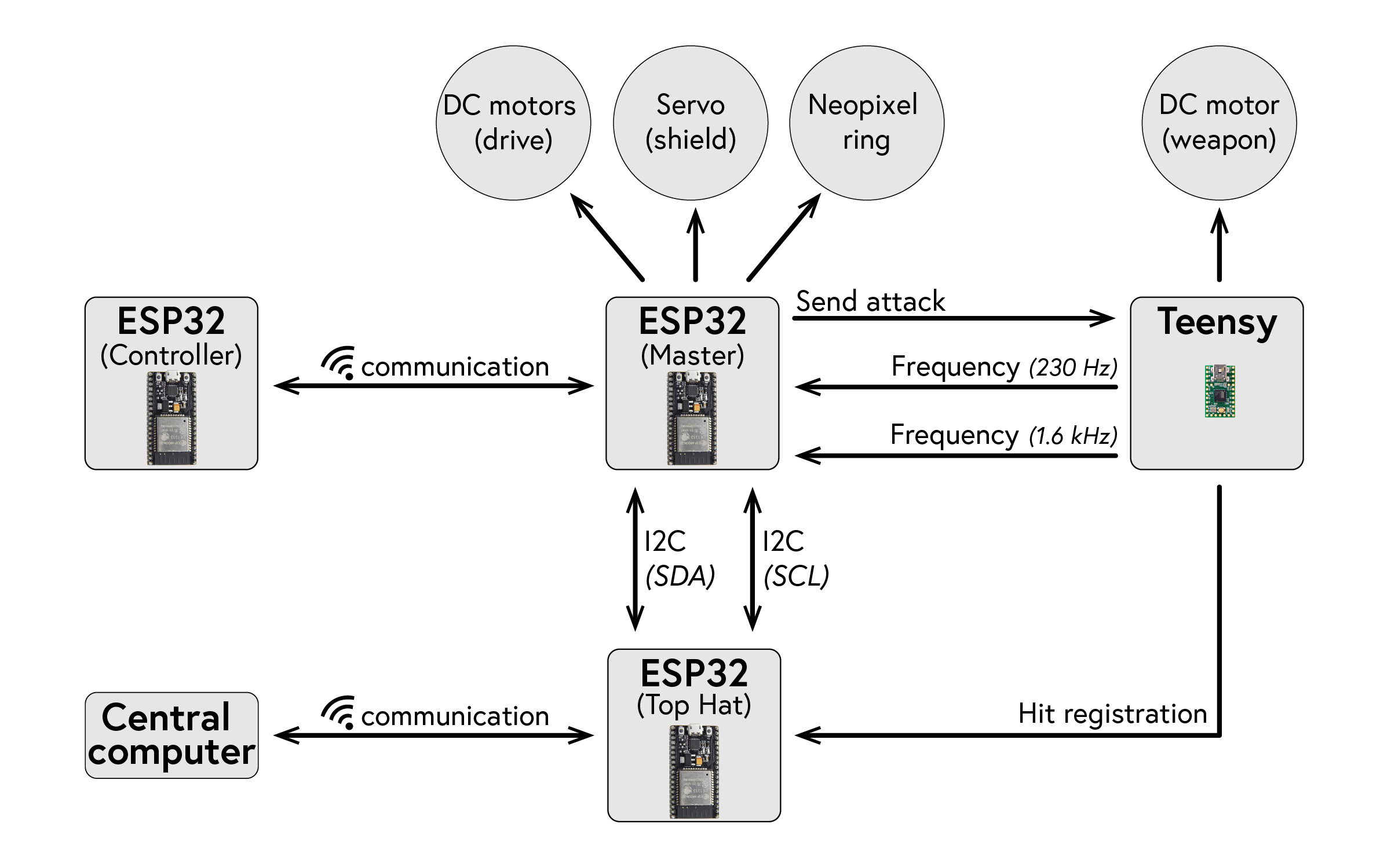
We used the Teensy 2.0 micro controller (ATmega32U4) and the ESP32 (NodeMCU 32S) micro controller, programming both in C and Arduino. The E2P32 has WiFi capability. The controller has one circuit board, driven by an ESP32. The robot car has three main circuit boards onboard: it has one for the ESP32, which is the “master”, one for the Teensy, and one for the top hat control board (ESP32). The top hat control board was provided to us and was required for communication with the central computer which manages the game for all robots. The “master” ESP32 communicates with the controller wirelessly via WiFi, with the top hat control board via I2C, and with the Teensy control board via digital logic. It also contains the motor driver to drive the wheel motors, controls the servo for the shield rotation, and controls the Neo Pixels to display visual information on the top hat button. The Teensy circuit controls the weapon arm motor as well as processes the PWM frequency detection through input from a phototransistor.
The robot is powered by three battery packs: a 7.4V LiPo battery, a 9V battery, and a battery holder containing four AA batteries (6V). The 9V battery is regulated down to 5V. This 5V source powers the Teensy micro controller and the motor driver. The LiPo battery powers the master ESP32 and the top hat control board (ESP32). The 6V source powers the two driving motors and the servo.
PROCESS
Design process & documentation